
Zodiark Build Guide

Starting off
Start off soldering on the surface mount components (Diodes, LEDs, Hotswap Sockets) to the bottom of your boards.
materials
The PCB kit comes with:
2x Zodiark PCBs
70x T4 SMD Diodes
68x SK6812 MINI-E RGB LEDs
68x Kailh Hotswap Sockets
2x 6mm Reset Tactile Buttons
2x TRRS Jacks
4x Pro Micro hotswap headers
2x OLED hotswap headers
Not included in the PCB kit is:
68 MX Style switches and keycaps
2x EC11 Encoders with knobs
2x Pro Micro or equivalent MCU
2x .96 128x64 I2C SSD1306 OLED or .91 128x32 I2C SSD1306 OLED
Top/Bottom Plates or Case
Stiff wire or discarded through hole diode or LED legs for the hotswap MCU sockets
The FR4 Plate case kit comes with:
2x Top Switchplates
2x Bottom Plates
26x 7mm M2 Standoffs
52x 4mm M2 Button Head Screws
Not included in the case kit:
Silicone/rubber feet
Required tools:
Soldering Iron and Solder
Small tweezers
Small M2 hex screw driver (for the case kit)
(Recommended) Flux
Diodes
Start by adding solder to a single pad on each diode footprint.
Next use tweezers to place the diode on the pads, make sure the line on the diode is matching up with the thicker line on the top of the board diode footprint.
Reflow the solder with your iron to attach the diode to the board.
Finally, fully secure the diode by soldiering the bottom leg.
NOTE: Make sure not to miss the sideways diode under the encoder.


Hotswap Sockets
Place your hotswap sockets, make sure they are oriented not blocking the middle switch stem hole.
Place your soldering iron tip touching both the pad and the metal leg of the hotswap socket, feed in solder until you see the pad coated and the scoop of the leg is about half full with solder.
While solder is still flowing with your iron touching it, push down on the hotswap socket (recommend not using your finger for this, try using tweezers) so that it remains flush with the board, remove your iron while holding the socket down until the solder solidifies.
Repeat step 2 and 3 with the other leg.


sk6812mini-e LEDs
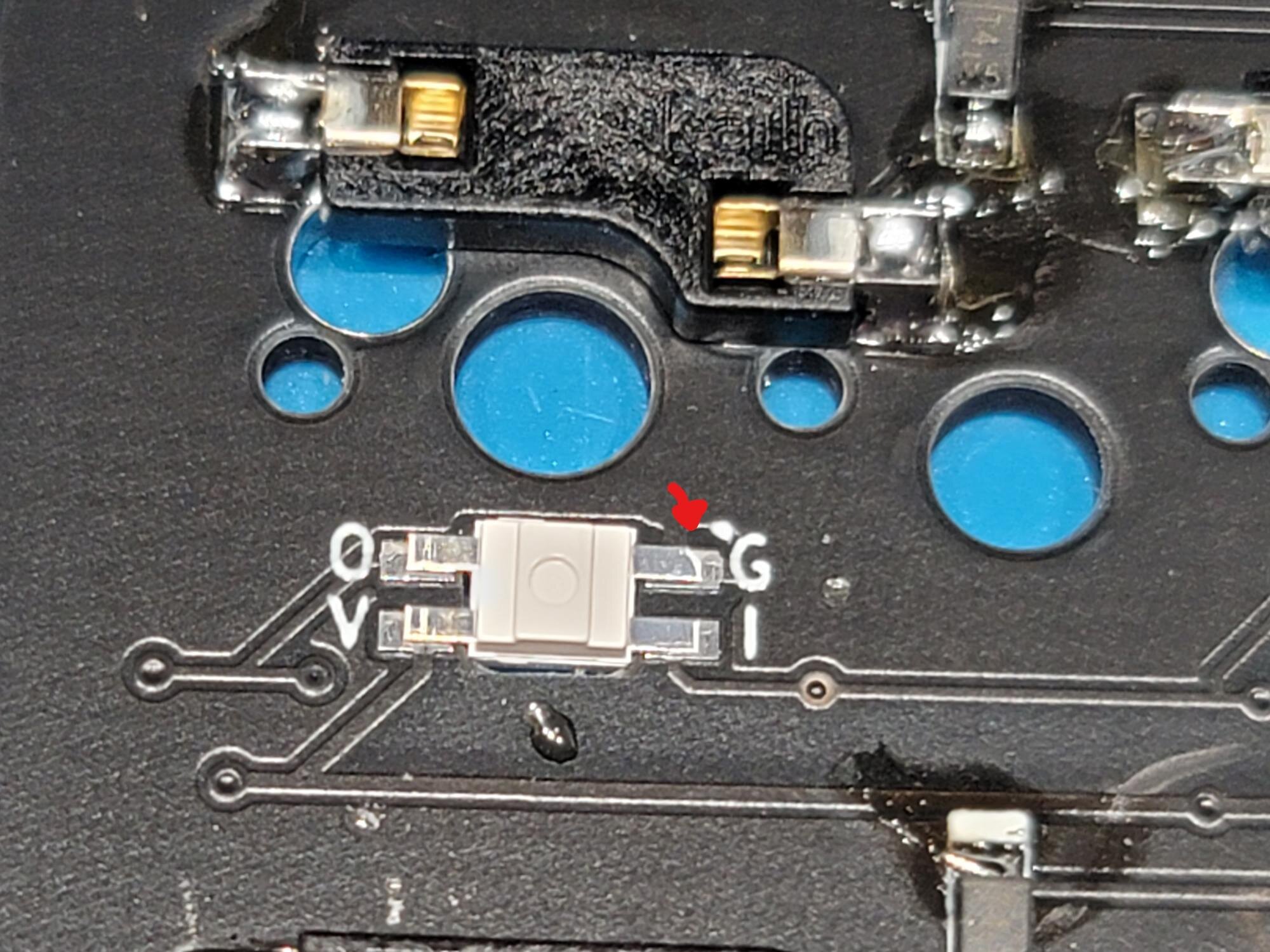
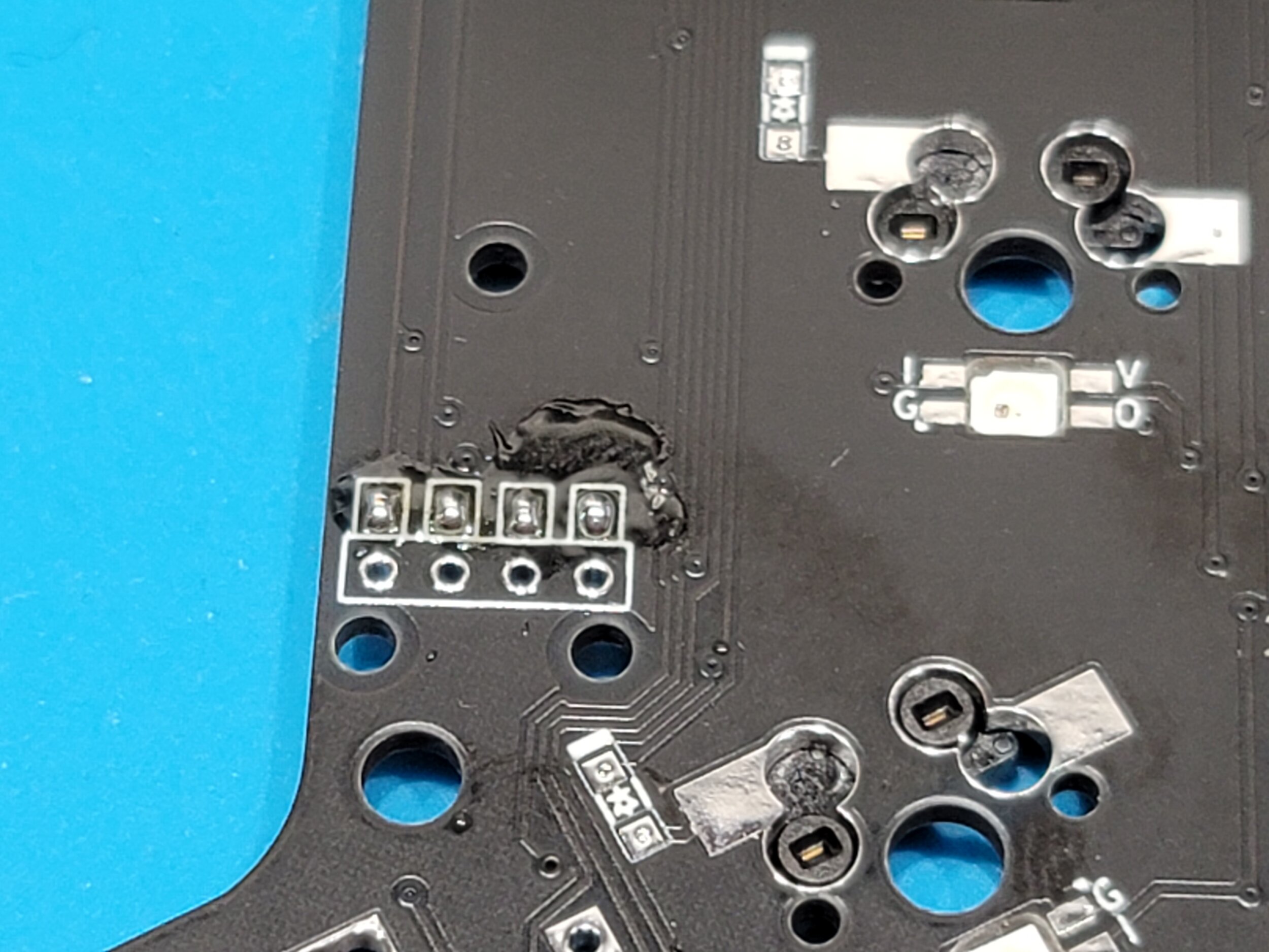
Make note of the LED leg with a notch in it, this is the Ground pin for the LED and will always match up with the “G” marking on the board. NOTE: The corner where the “G” mark is will change each row, so make sure to pay attention to where the marking is when you change row.
Press fit the LED into the hole, facing downward.
Solder down each leg. NOTE: The “G” pad will be attached to the ground pour, so you may need to leave your iron on that one a bit longer to get it up to a temp that will allow solder to attach.


Pro Micro
NOTE: All the rest of the through hole components such as the Pro Micro, TRRS jack, Reset Button, OLED socket, and Encoder will be soldered to the TOP of the board.
Included in your kit will be a strip of hotswap socket strips for your pro micro, it is up to you if you wish to use those, or use the normal pin strip that came with your Pro Micro.
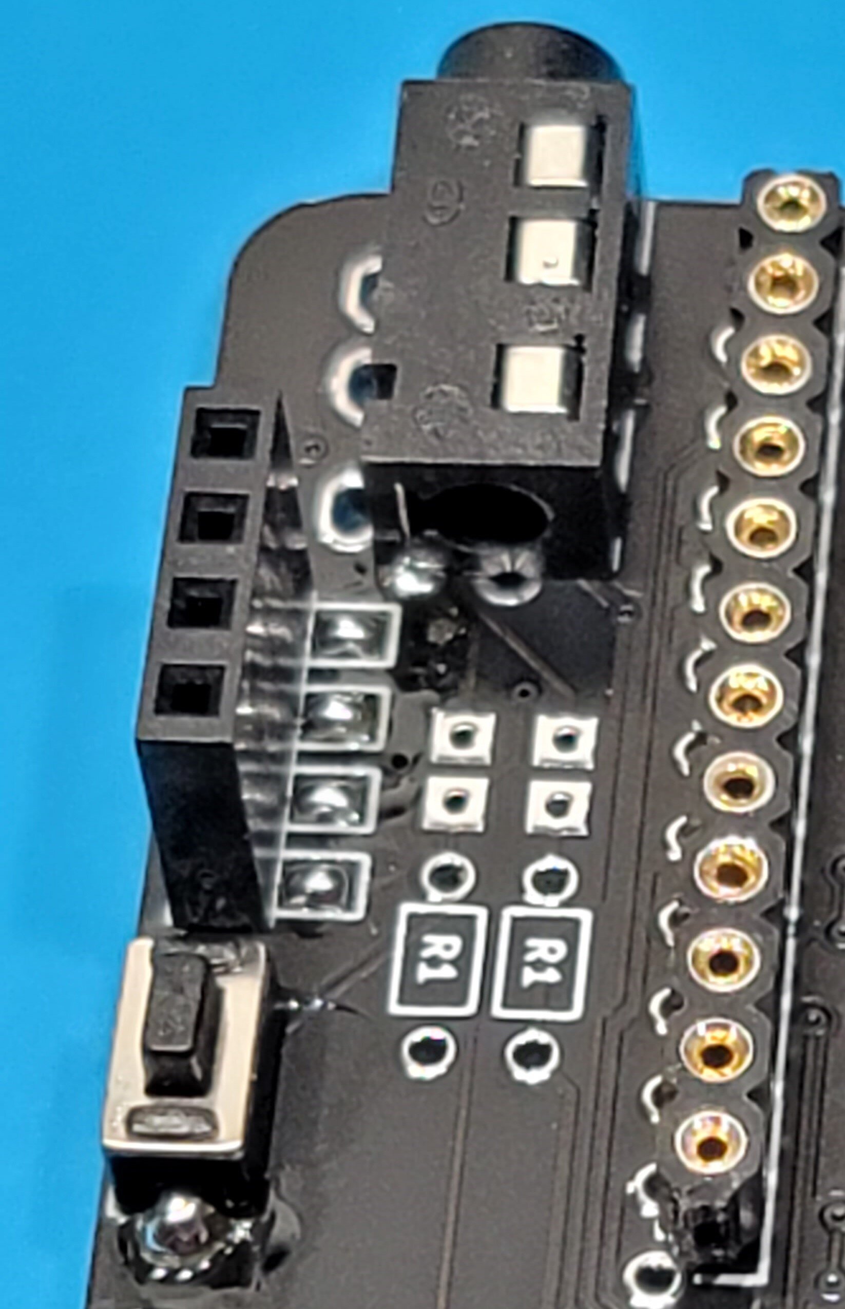
Make sure to use the set of holes on the top of the board that are outlined as follows:

Before soldering to your Pro Micro, now would be a good time to pre-flash it to confirm you have a functioning Pro Micro. Using QMK toolbox, load up your .hex firmware file, check “Auto-Flash”, attach the Pro Micro to your computer with a USB cable, and using metal tweezers or a piece of jumper wire, short out the GND and RST pins on the Pro Micro, you should see it start the flashing process, and then when its finished you should see “Zodiark” being set up.

If you use the hotswap socket strip, you will need to provide some sort of pin to attach the two, it is recommended to use something like discarded through-hole diode or LED legs to connect your Pro Micro to the hotswap strip. I use painters tape to hold the sockets onto the board, I solder the top pin in, and the reflow that solder, and use my finger (Make sure you aren’t holding the strip on top of the pin you’re heating up) and move it flush and perpendicular to the board, then removing the soldering iron to solidify it in place, I then continue to solder the rest of the pins in. Repeat for the other row of pins. Then you’ll leave the painters tape on, poke holes through the tape for each socket, place your Pro Micro on top of the tape (normally with the components facing down towards the board), push the diode through the hole on the Pro Micro into the hotswap socket, making a good connection, and then soldering that pin down to the pro micro, the tape will act as a barrier keeping the solder from going into the socket. Repeat for all pins. Once you’re finish, carefully remove your Pro micro from the socket (Accompanying Pictures for this process coming soon.)
TRRS, OLED Socket, RESET BUTTON, Encoder
NOTE: All the rest of the through hole components such as the Pro Micro, TRRS jack, Reset Button, OLED socket, and Encoder will be soldered to the TOP of the board.
Place the TRRS jack on the top of the board, and solder down
Place the Reset button on the top of the board, and solder down
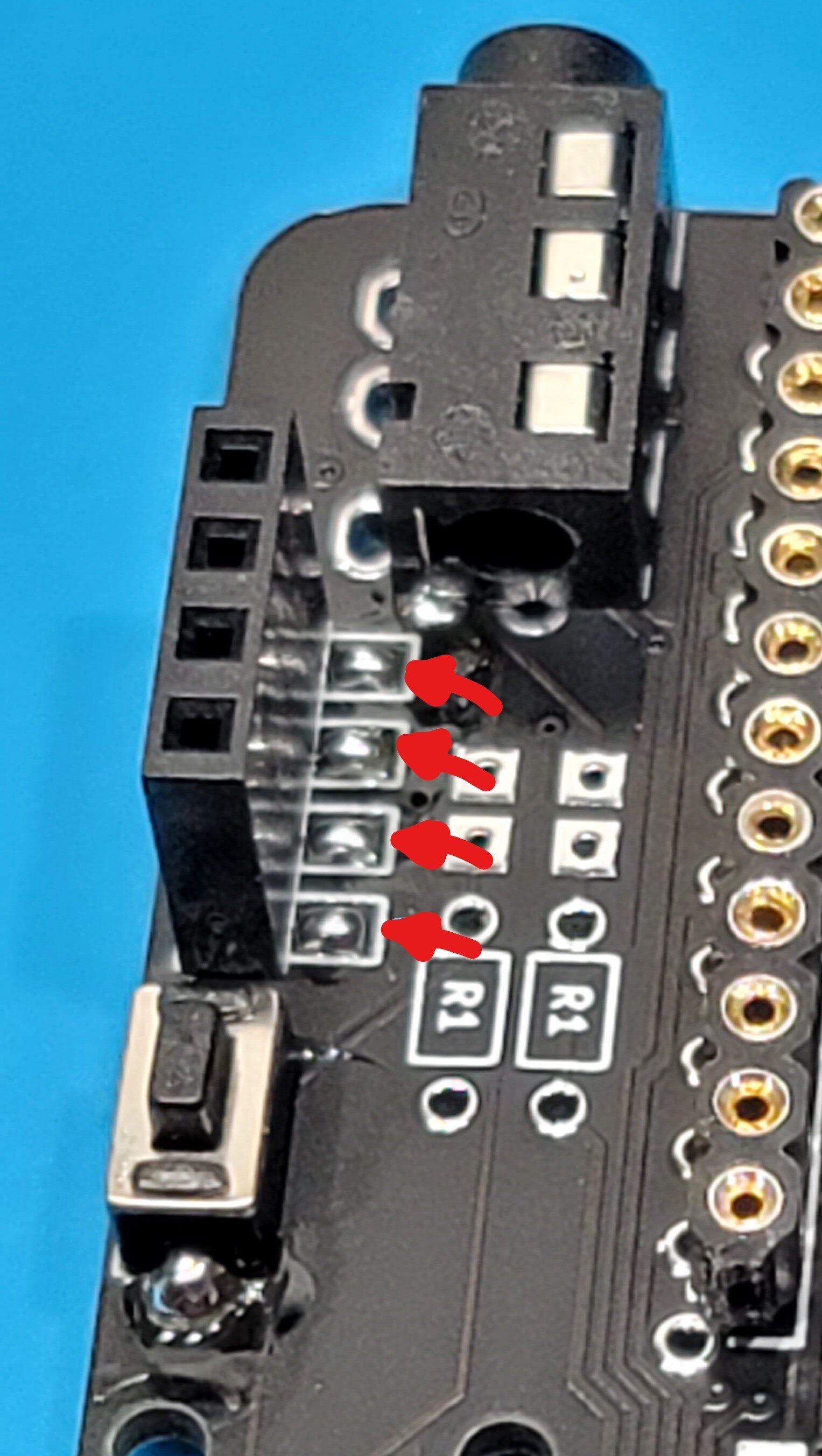
Bridge the jumpers on the top of your board for where you want your OLED (Position near the TRRS and Reset button for 128x64 OLEDs, position above the encoder for 128x32 slim OLEDs). NOTE: Recently, some OLEDs have been shipping out with the GND and VCC pins swapped, the normal pinout is GND-VCC-SCL-SDA, some new OLEDs have been shipping with VCC-GND-SCL-SDA, causing them to not work. Using small wires to cross over the two top/left most jumpers would fix this issue, but these jumper points are very small and close to each other, making this difficult. Another solution may be presented in a later revision if OLEDs continue to ship out like this regularly.
Place the OLED socket (Position near the TRRS and Reset button for 128x64 OLEDs, position above the encoder for 128x32 slim OLEDs), and solder down.
Place the Encoder, and solder down
Finishing Touches
Once you’ve followed these steps for both halves, you should at this point have a fully assembled board minus the case, keyswitches, and keycaps.

If flashed with the default keymap, the left side is the master by default, and you should see all the LEDs light up red by default, and the OLEDs should come on. At the point, I would grab a spare keyswitch, and test out each hotswap socket for activity before assembling the case.


Common issues
One of my keys isn’t working
Make sure that all diode legs are soldered down
Check the hotswap socket leg, did solder flow out onto the pad from the socket leg?
Only some of my LEDs are working
Start at the last LED that is working in line, is the “O” pin properly soldered down?
On the first LED that isn’t working, reflow all the pins, recommend using a bit of flux for this if you have some.
OLEDs aren’t coming on
Check if you made a complete bridge on each of the 4 jumpers on the TOP of the board.
Look at the pinout of your OLED, it should be GND > VCC > SCL > SDA, lately some suppliers have been shipping OLEDs with the GND and VCC swapped, and those wouldn’t be supported without some sort of either wiring from the OLED directly to the through holes, or bodge wiring the jumpers, which would be difficult due to the small size of the jumpers.